
A digital filter is a signal processing system that performs mathematical operations on a sampled a continuous signal that has been reduced to a discrete one discrete-time unlike the continuous signal the discrete one does not have a value at every instance of time - it is quantized digital a physical signal that is a representation of a sequence of discrete values. 2 drum machines in.
Fir
How To Accelerate A Simple 16 Bit 12 Tap Dsp Fir Filter By Compiling It Into Fpga Hardware Signal Processing Design

Fpga Ip Builder Tutorial Fpga Ip Builder Labview 2013 Fpga Ip Builder Help National Instruments
You can design your algorithms and iterate through them using high-level performance-optimized blocks and validate functional correctness through system.

Dsp filter design tutorial. Within our DSP portfolio we have a selection of full-featured development and reference examples for a tailored system solution. MSK as a special case of both non-linear and linear modulation schemes. Inverse Sinc Finite Impulse Response Filter Design.
The system shown in Figure 1 is a real-time system ie the. FIR Designer M is the most comprehensive providing integrated design for up to 6-way loudspeakers. Before proceeding with this tutorial the readers are expected to have a basic understanding of discrete mathematical.
Synopsys power analysis tutorial can be found here. Intro to the Simplified C Block 0419 Processor-in-the-Loop PIL simulation with PSIM -. The tool is written in Perl.
1 When compared to our competitors 7nm FPGAs Intel. The lowpassbandpass filter is required to remove unwanted signals outside the bandwidth of interest and prevent aliasing. Connector panel CP1104 3.
When we design and simulate the high-level either behavior or RTL code we only care about design functionality. Along with it in this tutorial we have shown the filter design using the concept of DSP. Our portfolio of DSP evaluation boards help you demo or provide proof of concept through the evaluation and validation phases of your design.
Using HLS IP in System Generator for DSP This tutorial shows how RTL designs created by High-Level Synthesis can be packaged as IP and used inside System Generator for DSP. The stream of 1s and 0s is subsequently digitally filtered not shown to produce a slower stream of multi-bit samples. Digital signal processing deals with the signal phenomenon.
The graphic interface is made up of a 18in ST7735 color TFT display which comunicates via SPI data interface. I can test the filter with a sweep generated by the DSP from say 15khz - 100khz and make sure the filter is doing the job. Typical Sampled Data System.
How can a modulation be both non-linear and linear. This tutorial has a good balance between theory and mathematical rigor. Their DFTs are X1K and X2K respectively which is shown below.
Analog Filter Design The functions iirdesign iirfilter and the filter design functions for specific filter types eg ellip all have a flag analog which allows the design of analog filters as well. Inside the Si473x IC the radio frequency signal is digitalyzed thru AD converter and processed by the DSP digital signal processor and then converted to audio thru DA converter and sent to. We can see from the first figure that the attenuation in the stopband exceeded our specifications perhaps we can tweak the attenuation and passband frequency to enhance the design.
I hope it helps to you too. -7000 SoC design this tutorial shows how the C driver files created by High-Level Synthesis are incorporated into the software on the Zynq Processing System PS. The verification and design for the concentrator of a Knockout Asynchronous Transfer Mode ATM switch fabric has been carried out by utilizing the VIS device in this project.
If you need help on Filter Design choosing filter Specifications creating a special filter structure or any Digital Signal Processing questions in general contact me. Understanding the basic FIR filter is a stepping stone to understanding more complicated filters such as polyphase FIR filters and adaptive FIR filters. As we see later in this tutorial originally MSK is a non-linear modulation but a certain depiction of its actual digital symbols known as pseudo-symbols turns it into an OQPSK representation.
The following figure shows the connections between the system and its controller. Real-Time and the Structure of a Real-Time Program Suppose we have a continuous system and we want to control it with a discrete controller which has sampling time period of T. Both FIR Designer products have unlimited IIR filters filter prototypes automatic correction frequency bands and project Windows as well as built-in measurement Averaging Continuous Wavelet Display Coherence functionality.
The sigma-delta modulator loop typically runs at a much higher frequency than the final output rate of the digital filter. For example a converter with a 2kHz output data rate may have a modulator loop frequency of over 25MHz. The RTL design that is structural well as a higher-level model that is behavioral of Knockout switch concentrator in Verilog HDL has been developed.
In comparison the largest-magnitude coefficients of a minimum-phase filter are nearer to the beginning. The bandwidth of the filter is always specified to the -3dB point so in the first iteration of design our filter has a smaller bandwidth than specified somewhere less than 9kHz. As we expected FIR digital filter has the biggest power consumption because it has a more complex circuit doing DSP computation.
The output shown in the figures below shows the differences between the RRC- and RC-filtered symbols. At this point you would be thinking about the following question. How to Use the PSIM DSP Oscilloscope for real-time DSP control 1005 C code simulation with PSIM.
Explore a selection of our more popular hardware resources. As I type this I realise it may have been more sensible to breadboard the buffer with the filter and test it 1st before sending off for the pcb. Intels highest performance FPGA family with family members in production today has the industrys leadership position for FPGA performance and power efficiency providing 45 higher performance geomean 1 and up to 40 lower power relative to previous generation Intel Stratix 10 FPGA family.
In this lesson I will show how to code a finite impulse response FIR digital filter in the C programming language using floating point operations. Synthesis with Timing Constraints. Wollo Beat is a virtual drum and percussion machine which combines old Roland style sounds with acoustic sampled sounds.
N-BIT ADC DSP N-BIT DAC LPF OR BPF f a t f s f s AMPLITUDE QUANTIZATION DISCRETE TIME SAMPLING f a 1 f s ts Figure 1. The second RRC filter here converts the signals from using the non-Nyquist RRC filter to a Nyquist raised cosine RC filter as we discussed in the first stage of this tutorial. DSP - DFT Circular Convolution Let us take two finite duration sequences x1n and x2n having integer length as N.
Wollo Beat is a free drum machine and rompler VST plugin developed by Erik Wollo. Vitis Model Composer is a Model-Based Design tool that enables rapid design exploration within the MathWorks MATLAB and Simulink environment and accelerates the path to production on Xilinx devices through automatic code generation. This tutorial explains how to generate an inverse sinc filter in liquid-dsp to compensate for the distortion caused by rectangular sinc filters commonly implemented in hardware.
Breakthrough Intel FPGA News. The example below designs an analog IIR filter obtains via tf2zpk the poles and zeros. See dspGurus tutorial How To Design Minimum-Phase FIR Filters for.
A quick guide for DSP design is provided to help understand the FIR filter design. A lowpass FIR filter has its largest-magnitude coefficients in the center of the impulse response. I use this tool to design FIR filters.
Tutorial Demystifying Digital Filters Part 1 Cycling 74


An Astounding Digital Filter Design Application Rick Lyons
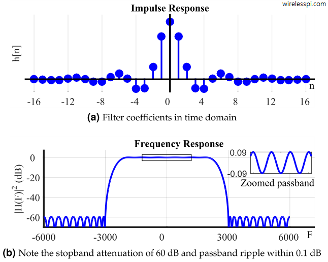
Finite Impulse Response Fir Filters Wireless Pi

Tutorial Basics Of Choosing And Designing The Best Filter For An Effective Data Acquisition System Edn

Micromodeler Dsp Infinite Impulse Response Filter Design Tutorial
Fir Filter Guide For Loudspeakers Finite Impulse Response Filtering Concepts Applications Youtube

The Complete Fir Filter Guide For Loudspeakers Audio Eclipse Audio

Fir Designer


